Check the package
One ZDK-01 controller per existing store order unit. Set excitation / holding voltage and transfer interval for the actual brake-coil requirement.
Confirm delivery →INTEGRATION ACCESSORIES
1 controller per order | AC 220 V input | DC 20-220 V adjustable output | 10 A | H/L/S setup
Check included items, availability and delivery before placing your evaluation order.
Model-specific values and test conditions.
| Parameter | Published value / condition | Ref. |
|---|---|---|
| Product name | Elevator brake power controller | E1 |
| Model | ZDK-01 | E1 |
| Sales unit | 1 controller per order quantity | E1 |
| Input supply | AC 220 V | E1 |
| Output voltage | DC 20-220 V adjustable | E1 |
| Output current | 10 A reference from supplied product details | E1 |
| Input terminals | L, N | E1 |
| Output terminals | B+, B- to brake coil | E1 |
| Parameter modes | H: excitation voltage; L: holding voltage; S: transfer interval | E1 |
| Controls | SET, Up, Down | E1 |
| Signal / item | Source reference | Ref. |
|---|---|---|
| L / N | AC 220 V line / neutral input · Source PDF p.4; power disconnected before wiring | E2 |
| B+ / B- | DC brake-coil output · Input and output must not be interchanged | E2 |
| H / L / S | Excitation voltage / holding voltage / transfer interval · Panel parameter modes, not terminal names | E2 |
Units: mm. Source dimensions only; unavailable details are TBD.

| Item | Published value / condition | Ref. |
|---|---|---|
| Overall length / width / height | TBD / TBD / TBD | E2 |
| Installation hole diameter / spacing | TBD / TBD | E2 |
| Terminal pitch / enclosure clearance | TBD / TBD | E2 |
| Mass / thermal / insulation drawing | TBD / TBD / TBD | E2 |
| Capability | How it is provided |
|---|---|
| Device interface | Refer to model-specific documentation |
| MQTT | Acquisition and gateway integration available; model-specific scope to agree |
| OTA | Firmware and update lifecycle services available; compatible device scope to agree |
One ZDK-01 controller per existing store order unit. Set excitation / holding voltage and transfer interval for the actual brake-coil requirement.
Confirm delivery →Specifications, dimensions, interface notes and available SDKs.
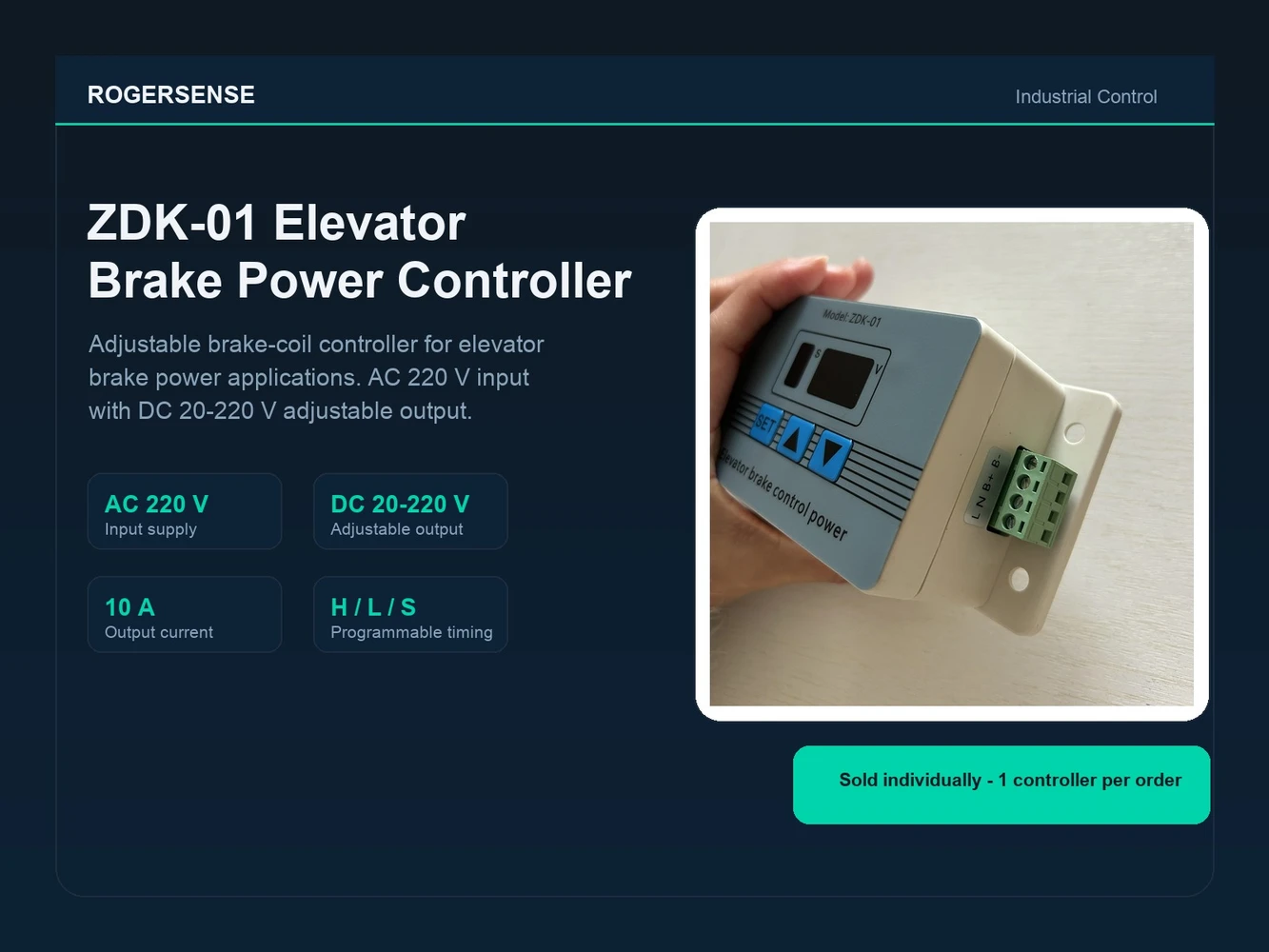
View documents →ZDK-01 Elevator Brake Power Controller is an adjustable brake-coil power controller for elevator brake and electromagnetic brake applications. It accepts AC 220 V input and provides a DC 20-220 V adjustable output for excitation and holding control. One online order quantity equals one controller.
| Product name | Elevator brake power controller |
| Model | ZDK-01 |
| Sales unit | 1 controller per order quantity |
| Input supply | AC 220 V |
| Output voltage | DC 20-220 V adjustable |
| Output current | 10 A reference from supplied product details |
| Input terminals | L, N |
| Output terminals | B+, B- to brake coil |
| Parameter modes | H: excitation voltage; L: holding voltage; S: transfer interval |
| Controls | SET, Up, Down |
No reviews yet.
