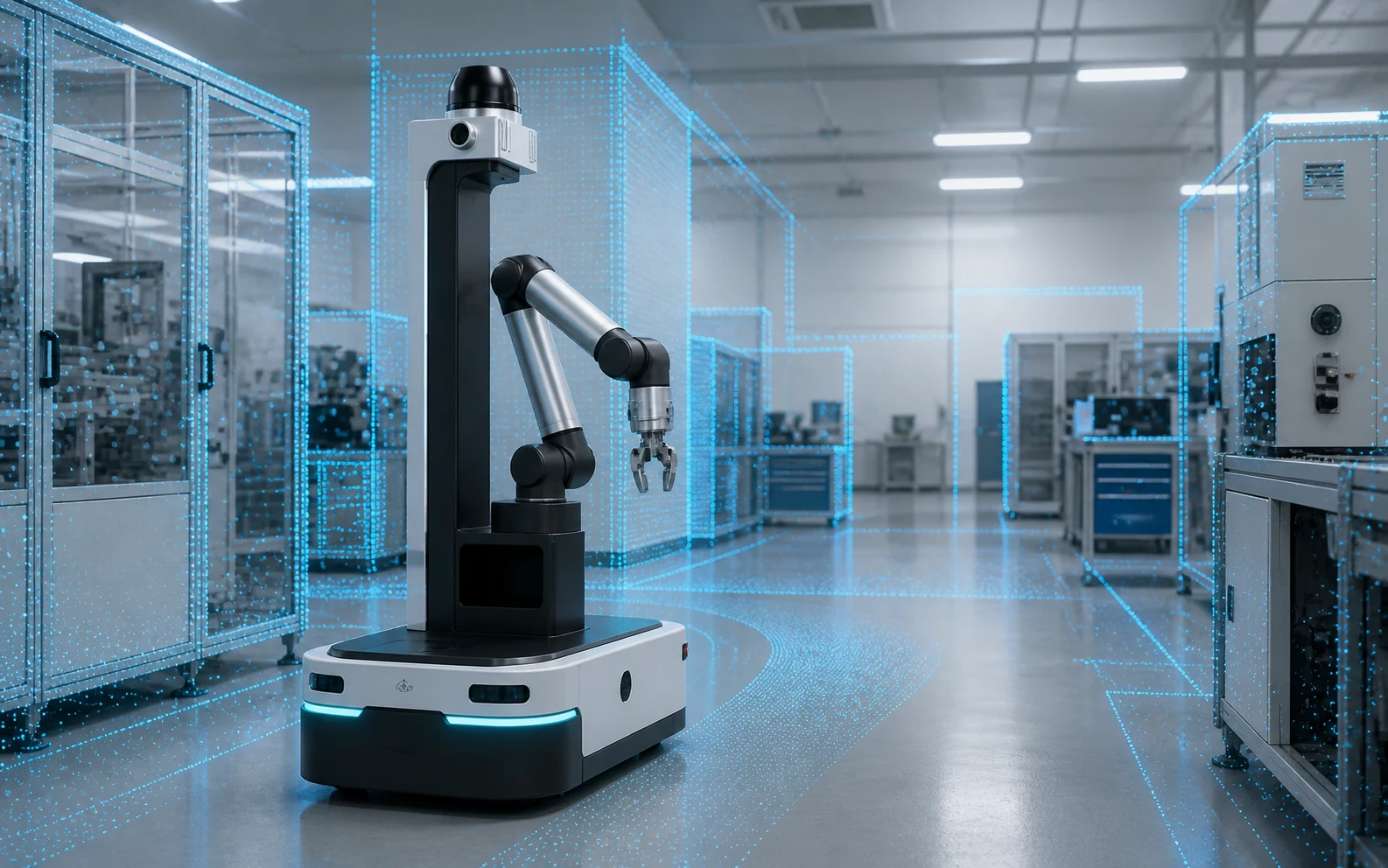
Humanoid robots and autonomous mobile robots are no longer confined to polished demos. BMW is extending humanoid work into logistics at its Spartanburg plant. Siemens and Humanoid are building around live factory targets. NVIDIA has introduced a full-stack robotics safety architecture for physical AI. The direction of travel is clear: AI is leaving the screen and entering shared industrial space.
The uncomfortable question is no longer whether a robot can complete a choreographed task. It is whether that robot can repeat the task through an entire shift while people, pallets, cables, tools, carts, reflective surfaces and changing light continuously rewrite the scene around it.
That is where what we call physical AI’s last 10 centimeters begins.
The phrase is not a formal safety term. It describes the difficult near-field zone between a robot’s ideal sensor coverage and its physical footprint—the area where a dropped fastener, a pallet toe, a cable loop or a worker’s shoe can turn an impressive pilot into a stop, a strike or an emergency intervention.
Why this question is suddenly urgent
The 2026 robotics news cycle contains two stories at once.
The first is deployment. BMW says its earlier Figure 02 program supported production of more than 30,000 BMW X3 vehicles over ten months, and the company is now moving to a Figure 03 logistics-sequencing use case. Siemens describes a factory deployment built around simulation, edge inference and real production targets. NVIDIA’s Halos for Robotics connects compute, sensor data, safety software and inspection, with outside-in cameras extending the robot’s own perception.
The second story is restraint. Gartner predicts that fewer than 20 companies will reach production-stage humanoid deployments in manufacturing and supply chain by 2028, and says the hype is running ahead of readiness.
Those stories are not contradictory. They point to the same transition: the industry is leaving the “can it move?” phase and entering the “can the whole system operate reliably?” phase.
Once a robot enters a brownfield factory, perception becomes a systems problem:
- A camera may recognize a worker but lose depth confidence on an untextured floor.
- A planar scanner may protect one horizontal slice but miss an object below or above that plane.
- A long-range 3D sensor may still have a near-field gap created by mounting height, housing geometry or self-occlusion.
- A strong model can still make a poor decision if timestamps drift or a sensor packet arrives late.
- A successful demo can hide rare edge cases that appear only after thousands of repeated cycles.
This is why the hottest robotics conversation is shifting from raw capability to coverage, validation and safety architecture.
The “last 10 centimeters” is a geometry problem
Near-field perception is not simply long-range perception with a smaller distance value.
A recent manufacturing-AMR study notes that many critical interactions happen within the first half-meter around the chassis, where small components, tools, cables and human limbs may appear unexpectedly. The researchers also found that conventional ranging systems can provide broad awareness while still missing small objects close to the base.
1. Mounting height creates a hidden wedge
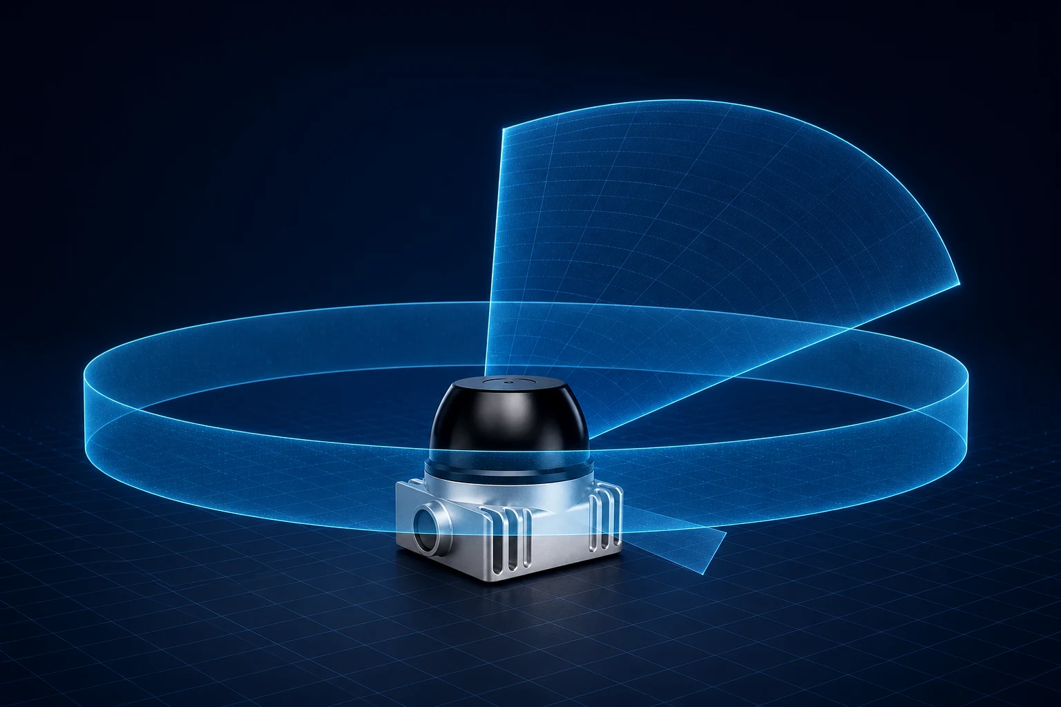
Move a sensor higher and its horizon improves, but the chassis can block downward sightlines. Move it lower and nearby geometry improves, but racks, payloads and people create more occlusion. The relevant question is not “Does this sensor have 360° coverage?” It is “What volume remains observable after the sensor is installed on this exact robot?”
2. Low-profile objects are hard in a different way
A pallet corner is large. A dark cable, metal strap, fork tip or dropped tool is not. Detection depends on more than nominal range: vertical field of view, angular sampling, target reflectivity, incidence angle, floor returns, motion and the perception pipeline all matter.
3. Close objects move rapidly through the field of view
At short distance, a small relative motion produces a large angular change. A person stepping around the rear corner of a robot can cross multiple perception zones quickly. Full-surround sensing reduces the handoff problem between front, side and rear sensors, but latency, timestamping and motion compensation still determine whether the geometry is useful.
A practical perception stack for factory robots
There is no universal sensor recipe. A robust architecture assigns different jobs to different layers.
| Layer | Best at | What to validate |
|---|---|---|
| 360° 3D LiDAR | Metric geometry, free space, obstacle shape and all-around localization | Installed minimum range, vertical coverage, dark/reflective targets, packet timing and motion distortion |
| Cameras | Semantics, text, gestures, object identity and fine appearance | Lighting transitions, blur, occlusion, privacy and failure behavior |
| IMU, encoders and joint state | Ego-motion and short-term state continuity | Drift, vibration, timing alignment and recovery after faults |
| Safety-rated protective devices and control | Risk-reduction functions required by the machine safety design | Standards scope, performance level, stop distance, diagnostics and validation |
| External or infrastructure sensors | Blind-corner and shared-zone awareness | Network dependence, calibration, coverage ownership and degraded mode |
NVIDIA’s new robotics safety architecture is directionally important because it treats compute, sensor connectivity, software and inspection as one system, rather than assuming a capable robot automatically becomes a safe deployment. ISO 3691-4 likewise addresses driverless industrial trucks and their systems—not just an isolated sensor.
That distinction matters: a perception LiDAR is not automatically a safety-rated protective device. It may improve environmental awareness and support navigation, mapping or obstacle detection, but the system integrator must determine the required protective functions through a formal risk assessment.
How to evaluate a 360° LiDAR for near-field work
Peak range is easy to compare and often the least useful number for an indoor robot pilot. Start with the installed geometry and the operational design domain.
Minimum range and vertical field of view
Treat minimum range as one input, not proof of chassis-level coverage. Plot rays against the robot envelope, payload and expected floor hazards. Then verify with the real bracket, bumper and cable routing.
Point rate, frame rate and angular sampling
A headline point rate only becomes useful when points land where obstacles actually appear. Check vertical channel distribution, horizontal sampling, frame rate and the number of returns. Record representative point clouds rather than relying on a live viewer alone.
Timing and sensor fusion
For a moving base, timestamp quality can matter as much as static accuracy. Validate network delay, packet loss, PPS/GPRMC behavior where used, IMU alignment, frame transforms and replay determinism.
Environment and surface behavior
Test matte black plastic, reflective metal, angled surfaces, shrink wrap, dust, direct light and dirty optical windows. A single white target at a convenient angle is a calibration check, not a deployment test.
Mechanical and electrical integration
Verify ingress protection, temperature range, vibration, connector retention, supply transients, power budget, heat rejection and service access. A sensor that works on a bench can still fail when the machine flexes or the cable intermittently loads the connector.
A pilot checklist designed to expose the blind zone
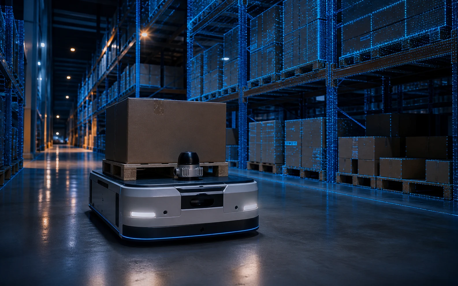
Before celebrating a successful route, run tests that are intentionally inconvenient.
- Place a cable loop, hand tool, pallet fragment and low dark object at multiple distances around the entire chassis.
- Repeat from front, rear and both sides while the robot is stationary, translating and rotating.
- Test at the mounting-height extremes and with the normal payload installed.
- Cross bright and dark zones; add reflective metal and low-reflectivity materials.
- Introduce a person from an occluded corner and validate detection-to-action latency.
- Record raw packets and fused outputs so failures can be reproduced offline.
- Interrupt sensor data, synchronization and network links; verify the defined degraded state.
- Measure braking and stopping behavior with the real load and floor condition.
- Repeat long enough to reveal thermal, contamination and intermittent-connection effects.
- Document every uncovered volume and assign it to another sensor, a mechanical change or an operating constraint.
This checklist is deliberately broader than a LiDAR acceptance test. The goal is not to prove that one sensor is good. The goal is to learn where the total robot is still blind.
Where a compact 360° LiDAR fits
For teams building AMRs, wheeled humanoids or mobile manipulators, a compact all-around LiDAR can consolidate geometric coverage and simplify the first perception prototype.
The Rogersense P60 is one option for that role. Its published integration specifications include a 360° horizontal by 60° vertical field of view, a 0.1 m minimum range, 96 lines, up to 960,000 points per second at 10 Hz, dual returns, PPS + GPRMC timing support, Ethernet connectivity, IP67 protection and a 65 × 65 × 61.5 mm enclosure.
Those numbers make the P60 relevant to the near-field conversation, but they do not eliminate the validation work above. Real coverage depends on mounting, target and environment, and final machine safety remains the integrator’s responsibility.
For an earlier look at complementary sensing, see our guide to validating LiDAR-camera fusion before an industrial robot pilot.
The bigger lesson: physical AI needs physical evidence
The next wave of industrial robotics will be won by teams that can turn surprising real-world behavior into repeatable engineering evidence.
That means fewer stage demos and more logged edge cases. Fewer arguments about the biggest model and more attention to sensor placement, timestamps, degraded modes and stopping behavior. Fewer claims that a component “solves safety” and more explicit ownership of every layer in the safety architecture.
Physical AI’s last 10 centimeters are not glamorous. They are where scale is decided.
Evaluate the P60 in your robot architecture
Review the P60, download the English or Chinese specification, and compare its installed coverage against your robot envelope. Rogersense can also help with mounting, synchronization, packet handling and pilot planning.
Frequently asked questions
What does “the last 10 centimeters” mean?
It is an editorial phrase for the difficult near-field region close to a robot’s footprint. It is not a formal industry zone or safety standard, and it should not be interpreted as a universal clearance requirement.
Is a 0.1 m minimum-range LiDAR guaranteed to see every object 10 cm from the robot?
No. Minimum range is a sensor specification under defined conditions. Installed coverage also depends on mounting height, vertical field of view, housing and chassis occlusion, target properties, motion and processing.
Can one 360° LiDAR replace safety scanners or bumpers?
Not by default. A 3D perception LiDAR can support navigation and obstacle awareness, but safety-rated protective functions must be selected and validated through the machine’s risk assessment and applicable standards.
Why combine LiDAR and cameras?
LiDAR provides metric 3D geometry, while cameras add semantic detail and appearance. Their failure modes differ, so fusion can improve capability when timing, calibration and degraded behavior are handled correctly.
What should teams record during a pilot?
Keep raw sensor packets or PCAP files, synchronized camera data where permitted, robot state, transforms, detections, planner decisions, fault events and the final control action. A failure that cannot be replayed is difficult to fix.
Sources
- NVIDIA Announces Halos for Robotics, June 22, 2026.
- BMW Group advances the use of Physical AI in production with Figure 03, June 25, 2026.
- Siemens and Humanoid bring Physical AI to the factory floor, April 16, 2026.
- Gartner predicts fewer than 20 companies will scale humanoid robots to production by 2028, January 21, 2026.
- Near-Field Perception for Safety Enhancement of Autonomous Mobile Robots in Manufacturing Environments, December 2025.
- ISO 3691-4:2023 overview.