Choosing between 2D and 3D LiDAR is not a contest between an old technology and a new one. It is a decision about what geometry your robot must observe, how much data the perception stack can use, and which failures the system must tolerate.
A 2D scanner can be the right answer for a warehouse AMR moving across a controlled, flat floor. A 3D 360° LiDAR becomes more valuable when the robot must see pallet overhangs, ramps, curbs, forks, cables, people at different heights, or terrain that does not fit into one horizontal slice. Paying for more dimensions only makes sense when the system can convert those points into better decisions.
What “360° LiDAR” actually tells you
The phrase 360° LiDAR usually refers to horizontal field of view. It says the sensor can observe around itself in azimuth. It does not tell you how much vertical space is measured.
A 2D LiDAR typically sweeps one horizontal plane and returns a set of range-and-angle measurements. A 3D LiDAR adds multiple vertical channels or another scanning dimension, creating a point cloud with x, y and z coordinates. Both may cover the full horizontal circle, yet they produce fundamentally different evidence for the navigation stack.
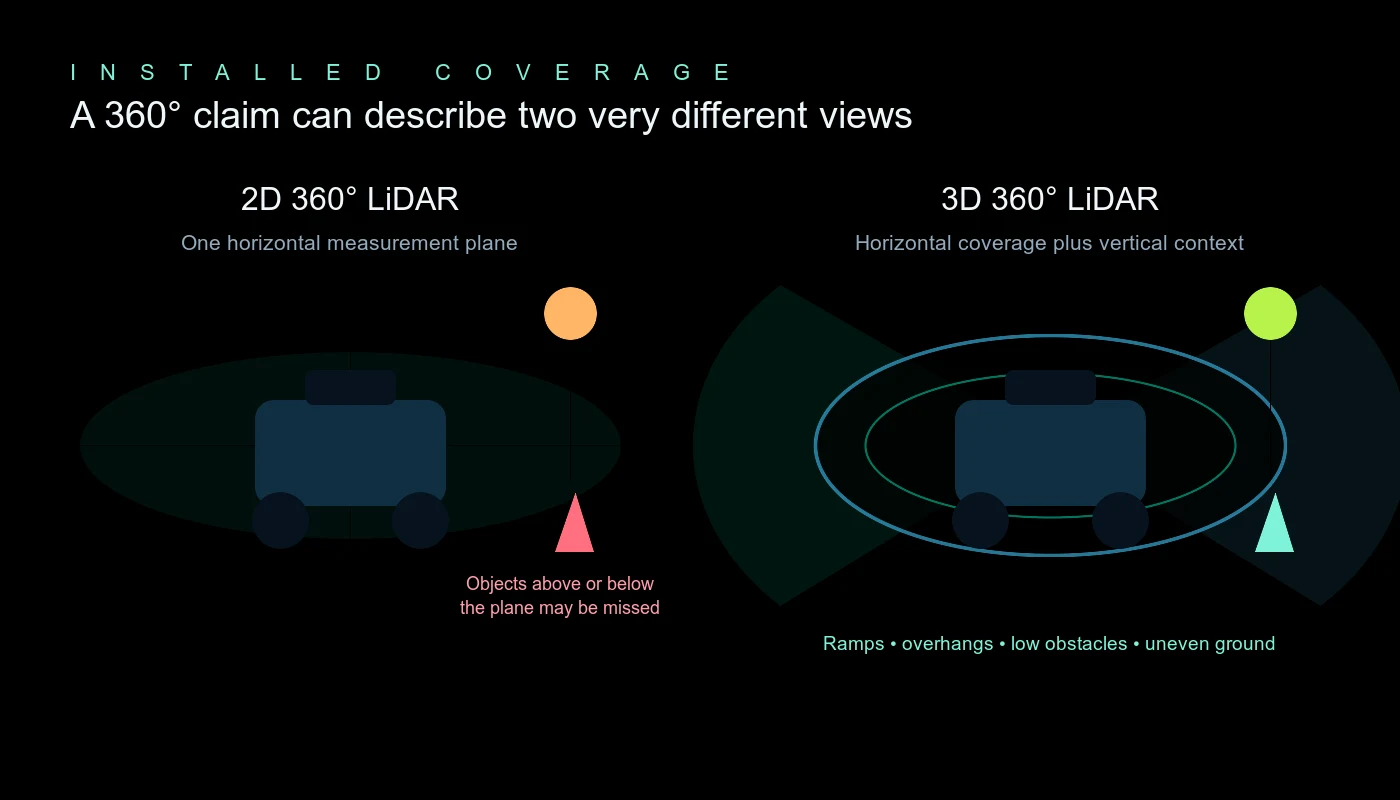
This distinction matters because a robot does not collide with an abstract point on a map. It collides with a physical object that has height, shape and an approach angle. If that object never intersects the 2D scan plane, the scanner may not provide a return even though its horizontal coverage is complete.
2D vs 3D LiDAR: the practical comparison
| Decision factor | 2D LiDAR | 3D LiDAR |
|---|---|---|
| Measured geometry | One scan plane | Volumetric point cloud with height |
| Typical strengths | Simple planar navigation, wall following, established localization, lower data load | Overhangs, ramps, curbs, ground segmentation, object shape, elevation change |
| Typical blind areas | Objects above or below the installed scan plane | Near-field or self-occluded regions created by housing and mounting geometry |
| Compute and network load | Usually lower | Usually higher; depends on point rate, frame rate and filtering |
| Calibration burden | Often simpler | Requires careful 3D extrinsics, timing and motion compensation |
| Mapping output | 2D occupancy map is natural | 3D map, elevation map, voxel map or derived 2D scan |
| Best fit | Controlled indoor routes with predictable obstacle geometry | Mixed-height, uneven, outdoor or semistructured environments |
| Cost of unused data | Low if a plane solves the task | High if the software discards height and uses only a thin slice |
The key phrase is usually. Some high-performance 2D scanners cost more than compact 3D units, and point-cloud pipelines can be efficient when they crop, downsample and publish only the information each consumer needs. Architecture matters more than the label.
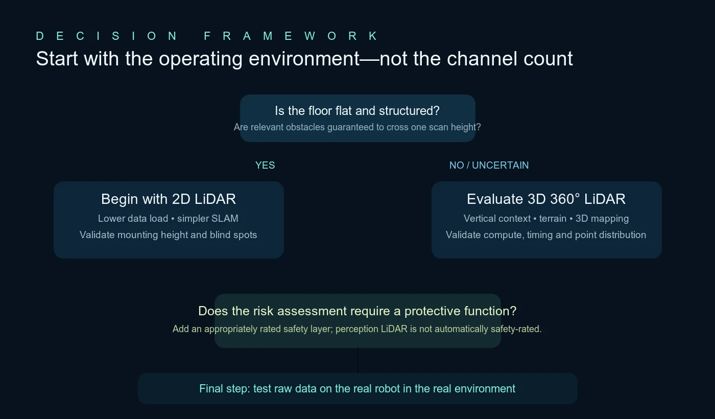
When 2D LiDAR is the better choice
A well-integrated 2D scanner remains one of the cleanest ways to obtain reliable planar ranges. It is often the better engineering choice when all of the following are true:
- The robot operates on a flat, controlled floor.
- Walls, racks, people and expected obstacles consistently intersect the selected scan height.
- The main outputs are a 2D occupancy map, planar localization and local obstacle avoidance.
- Power, processor capacity, bandwidth or development time is tightly constrained.
- Hazards outside the scan plane are covered by bumpers, depth cameras, additional scanners or another validated protection layer.
Typical examples include compact indoor carts, AGVs on fixed routes and low-speed AMRs in tightly governed facilities. A 2D pipeline is easier to inspect: each scan can be drawn directly against a floor plan, and mature SLAM and localization packages can consume it without a 3D segmentation stage.
That simplicity is valuable. Less data means fewer transformations, a smaller logging footprint, clearer latency budgets and often faster root-cause analysis. If a single plane genuinely contains the relevant world, 3D LiDAR does not automatically create business value.
When 3D LiDAR earns its place
Use 3D LiDAR when height is part of the decision. On real mobile robots, that happens more often than a clean warehouse diagram suggests.
Overhangs and objects outside one scan plane
A tabletop, protruding load, forklift tine, open cabinet, tailgate or pallet overhang can occupy the robot envelope while leaving the chosen 2D plane partially or completely clear. Multiple vertical channels give the planner evidence at more than one height.
Ramps, curbs, drop-offs and uneven terrain
A planar scan is not designed to describe the ground surface. A 3D point cloud can support slope estimation, ground segmentation and elevation maps for UGVs, outdoor delivery robots and mixed indoor-outdoor platforms. Drop-off detection still requires deliberate sensor placement and testing; a wide nominal field of view is not a guarantee.
Localization where walls are not enough
In long aisles or changing facilities, a planar map may contain repeated geometry. Structural features at different heights can add constraints for 3D localization. The benefit depends on the algorithm and environment: extra points do not repair poor observability by themselves.
One geometric layer for several consumers
A single 3D sensor can feed obstacle detection, localization, elevation mapping and a generated 2D scan. The official ROS 2 pointcloud_to_laserscan package demonstrates the last pattern: it converts a height-filtered point cloud into a LaserScan message. This can help a 3D sensor serve an existing 2D navigation component, but the chosen height limits still decide what information survives.
A decision framework that starts with failure modes
Do not begin with a sensor catalog. Begin with the obstacles and surfaces that could cause the robot to stop, collide, become stranded or lose localization.
- Define the operational design domain. Document floor condition, gradients, aisle width, speed, lighting, weather, dust, traffic, payload and human interaction.
- Build an obstacle library. Include the smallest, darkest, most reflective and most awkward objects the robot must handle—not only a person-sized target.
- Draw the installed sensor rays. Model the sensor on the actual chassis with its housing, bracket, payload and cable. Find self-occlusion and the near-field wedge.
- Assign each required function. Separate mapping, localization, navigation, semantic perception and safety-related protective functions. One sensor may contribute to several functions without being solely responsible for all of them.
- Budget data and latency. Calculate point throughput, network utilization, preprocessing, inference or segmentation time, planner update rate and worst-case age of information.
- Test the failure boundaries. Use degraded surfaces, packet loss, time drift, contamination and dynamic occlusion before selecting the final sensor.
The specifications that matter more than headline range
Range at a stated reflectivity
Maximum range without target reflectivity and test conditions is hard to use. For indoor mobile robots, performance on low-reflectivity material may matter more than the farthest bright target. Compare figures at a common reflectivity when possible and then test representative surfaces at the angles your robot will encounter.
Minimum range and installed blind zone
Published minimum range is measured at the sensor. The robot’s effective blind zone also includes mounting height, vertical field of view, chassis blockage and filtering. Plot where the lowest useful channels hit the floor. Then repeat the measurement with the payload attached.
Vertical field of view and channel distribution
A larger vertical field of view can help with near-field and elevation coverage, but channel placement also matters. Two sensors with similar vertical angles may distribute points differently. Ask for sample point clouds and determine how many useful returns land on your smallest target at the required distance.
Point rate, frame rate and scan pattern
High point rate is useful only if the spatial and temporal sampling support the task. Examine motion distortion during rotation, the repeatability of the scan pattern, multi-return behavior and the density that remains after cropping and downsampling.
Timing, interface and ROS 2 support
Confirm timestamp origin, Ethernet behavior, packet format, PPS or GNSS time input where required, IMU alignment, coordinate frames and driver maintenance. Record raw packets during a pilot so intermittent failures can be replayed instead of guessed at.
Mechanical and environmental fit
Size, mass, power, ingress protection, operating temperature, vibration, connector retention and heat rejection are system specifications. A sensor that performs on a bench can still be the wrong choice if its bracket flexes, its window becomes contaminated or its cable creates an intermittent fault.
Where the Rogersense P60 fits
The Rogersense P60 360° hybrid solid-state LiDAR is aimed at teams that need compact, all-around 3D geometry rather than a single planar scan. Its published specification includes:
- 360° horizontal × 60° vertical field of view
- 96 lines and up to 960,000 points per second at 10 Hz
- 50 m range at 10% reflectivity, with a listed maximum range up to 150 m
- 0.1 m minimum range
- 100BASE-T Ethernet, PPS + GPRMC timing, integrated IMU and dual return
- 65 × 65 × 61.5 mm enclosure, under 260 g, 7 W, IP67 and −40°C to +60°C operation
- Class 1 laser product
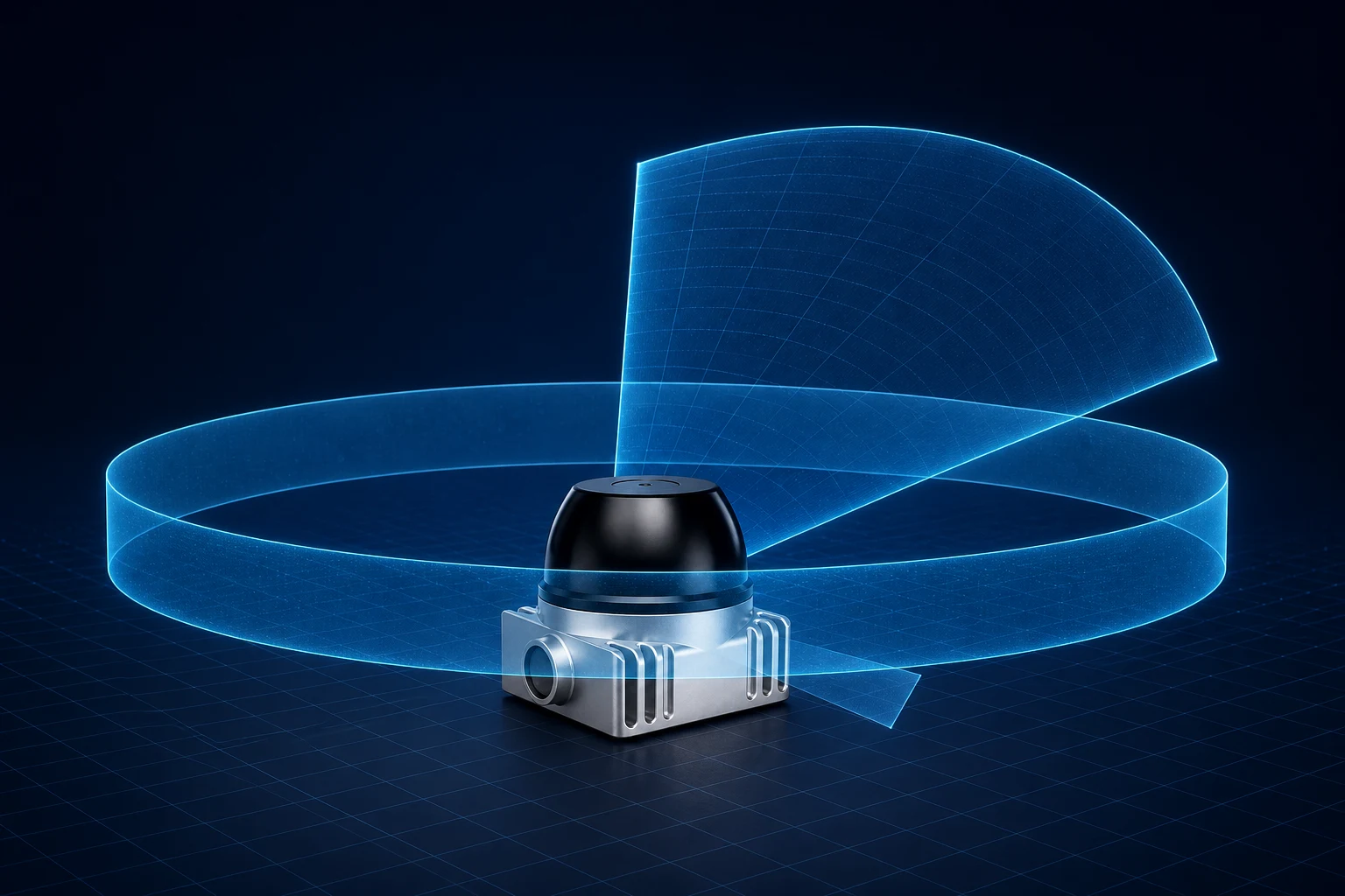
These figures make the P60 a candidate for AMRs, UGVs, mobile manipulators, mapping systems and research platforms that benefit from volumetric perception. They do not make it the right answer for every robot. If the application only needs a dependable scan plane, a 2D sensor may remain simpler. If the application requires a safety-rated protective field, the integrator must select and validate the appropriate certified safety functions.
For a deeper discussion of the space immediately around a robot, read Physical AI’s last 10 centimeters. If cameras are part of the architecture, use our LiDAR-camera fusion pilot validation guide to structure the test plan.
Published reference sensors: useful, but not a benchmark
The compact 3D market spans very different scan patterns and priorities. The examples below use vendor-published specifications to show the range of available designs. They are not a controlled performance comparison; definitions and test conditions differ.
| Sensor | Published FoV | Published range reference | Published point rate / mass |
|---|---|---|---|
| Rogersense P60 | 360° × 60° | 50 m at 10% reflectivity | Up to 960,000 pts/s at 10 Hz / <260 g |
| Livox Mid-360 | 360° × 59° | 40 m at 10% reflectivity | 200,000 pts/s / 265 g |
| Hesai JT16 | 360° × 40° | 30 m listed range | 200 g listed mass |
| Hesai JT32 | 360° × 42.6° | 65 m listed range | 192,000 pts/s / <200 g |
| Ouster OS0 | 360° × 90° | 35 m at 10% reflectivity | Up to 10.4 million pts/s |
Numbers alone do not show detection probability on a cable, glass behavior, motion distortion, driver quality or the points that remain after your filters run. Use specifications to create a shortlist, then use recorded evidence from the installed robot to make the selection.
A 10-step pilot checklist
- Install the production-intent bracket, cable and payload—not a temporary tabletop fixture.
- Measure the true sensor pose and verify the coordinate transform.
- Place low, high and overhanging targets around the full chassis perimeter.
- Test matte black, reflective, transparent or glossy surfaces relevant to the site.
- Drive straight, rotate in place and combine translation with rotation at the maximum planned speed.
- Log raw packets, timestamps, transforms, odometry and perception output on the same clock.
- Measure worst-case detection-to-action latency, not only average frame rate.
- Interrupt data, power or synchronization and verify the defined degraded behavior.
- Repeat across temperature, lighting, contamination and network-load conditions.
- Document every uncovered region and assign it to another sensor, a mechanical change or an operating constraint.
Common selection mistakes
1. Treating 360° as complete spatial coverage
Horizontal coverage can still leave a vertical or near-field gap. Always inspect the installed three-dimensional field of view.
2. Comparing only maximum range
A 100-meter claim may add little value to a robot that must detect a dark object at 30 centimeters. Start with the smallest critical target and its real surface.
3. Buying 3D data but building a 2D-only pipeline
If the stack immediately collapses the cloud into a thin plane, it may discard the height evidence that justified the sensor. Decide which downstream modules will use 3D information before procurement.
4. Ignoring timing because a static point cloud looks clean
Motion turns timestamp error into spatial error. Test while translating and rotating, and confirm how the driver stamps packets and frames.
5. Asking one sensor to own every function
Navigation, semantic understanding and safety-related protection have different requirements. Cameras, encoders, IMUs, bumpers and certified protective devices may all be necessary parts of the system.
Evaluate 360° 3D LiDAR on your robot
Review the P60 specifications, then compare its installed rays, data rate and interfaces with your chassis and software architecture. Rogersense can support mounting, packet handling, synchronization and pilot planning.
Frequently asked questions
Is 3D LiDAR always better than 2D LiDAR for an AMR?
No. A 2D scanner is often simpler and more efficient for flat, controlled environments where relevant obstacles cross the scan plane. 3D LiDAR is more useful when height, slope, overhangs, ground shape or mixed terrain affect the robot’s decisions.
Can a 3D LiDAR replace a 2D scanner in ROS 2 Navigation?
It can provide a height-filtered LaserScan through packages such as pointcloud_to_laserscan, or feed a voxel-based costmap directly. Replacement is an architecture decision: check latency, filtering, failure behavior and whether a safety-rated scanner is required for a separate protective function.
Does 360° LiDAR eliminate blind spots?
No. It eliminates a horizontal seam in nominal sensor coverage, but the housing, mounting height, chassis, payload and vertical field of view can create near-field and self-occluded regions. Validate coverage after installation.
How much LiDAR range does an indoor mobile robot need?
Enough to observe the required stopping and planning distance with margin under the worst relevant target reflectivity and incidence angle. Indoor selection should also prioritize minimum range, vertical coverage, latency and low-reflectivity behavior rather than maximizing range alone.
Is the Rogersense P60 a safety LiDAR?
The P60 is presented as a 3D perception sensor for mapping, navigation and obstacle-awareness applications. Do not assume it is a safety-rated protective device. Machine safety requirements and validated protective functions remain the system integrator’s responsibility.